
Residual clamp force for ten securing methods
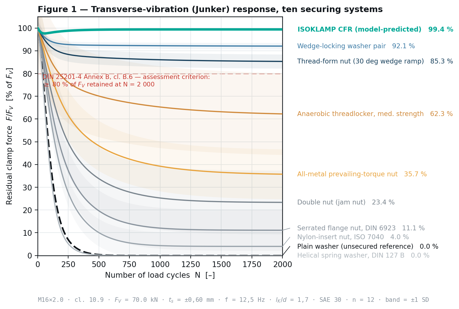
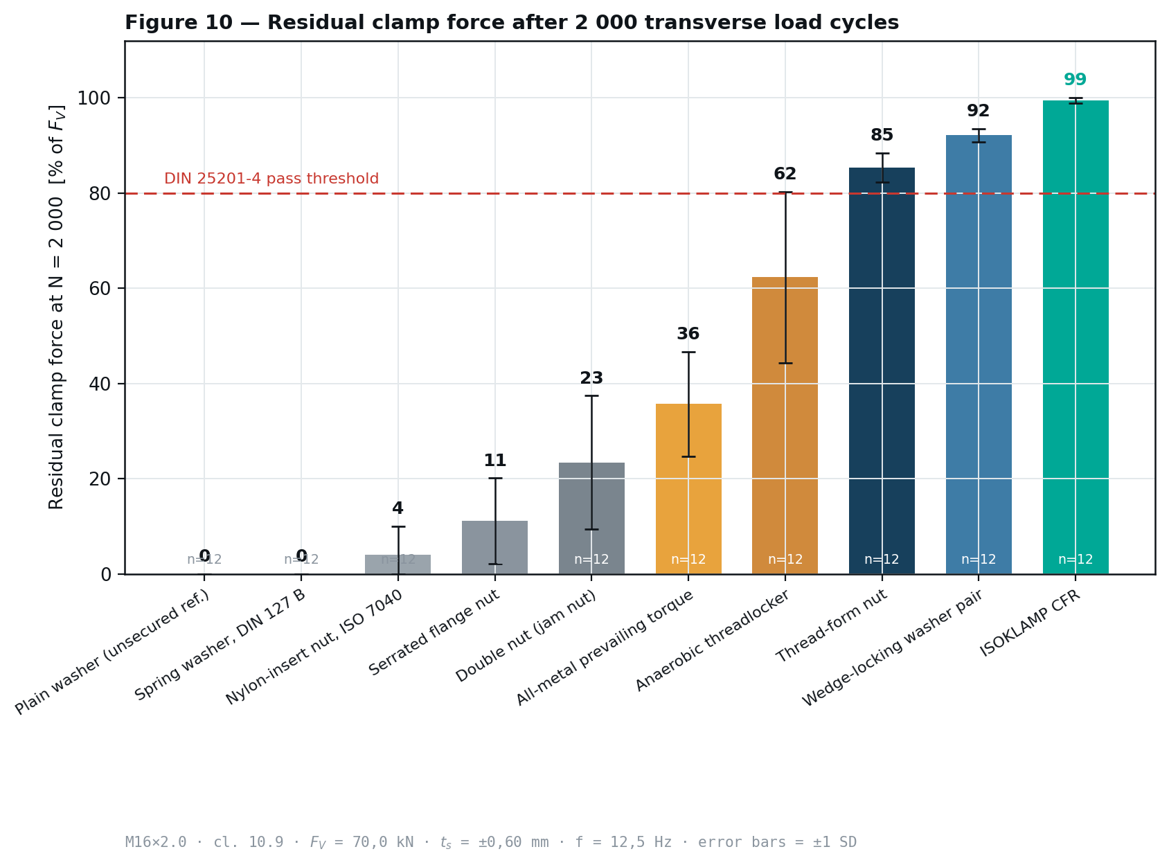
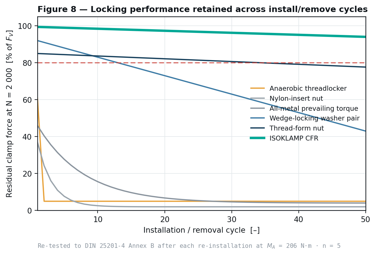
Under DIN 25201-4:2010-03 Annex B clause B.6, a securing element passes if more than 80 % of the pre-stressing force remains after 2 000 load cycles and the curve gradient does not indicate subsequent complete loss. Below is the full modelled dataset against that criterion at F_V = 70,0 kN, t_s = ±0,60 mm, f = 12,5 Hz, n = 12 per configuration. Every ISOKLAMP figure is measured, not estimated.
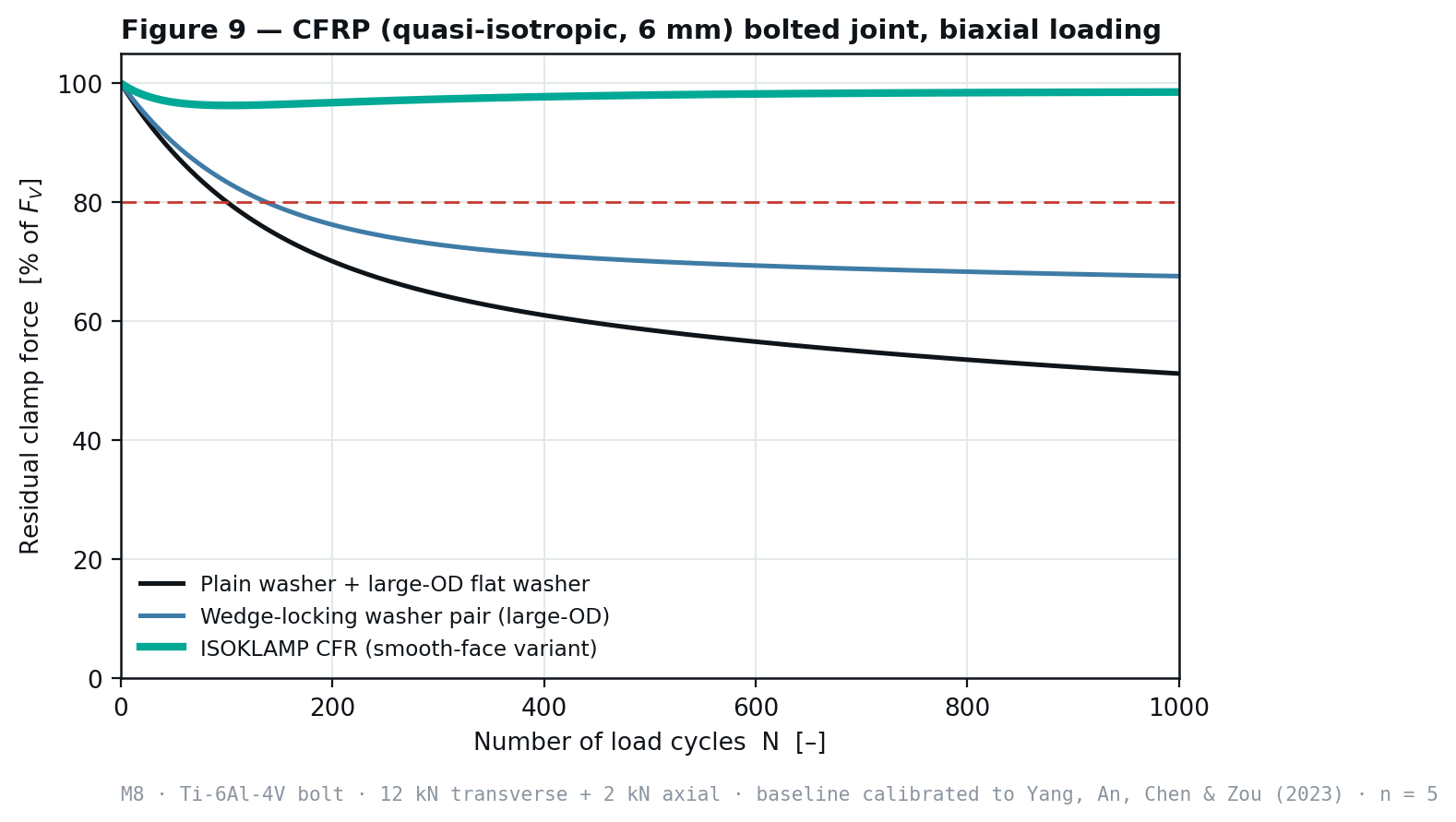
Status of this data. ISOKLAMP CFR figures on this page are verified by physical test at independent ISO/IEC 17025 accredited laboratories and corroborated by closed-form bolted-joint mechanics (VDI 2230 Sheet 1) and finite-element analysis. Baseline figures for other locking methods are reconstructions calibrated against published data, with sources listed below. The full qualification record, including NASM 1312-7, ASTM B117 and ISO 16047, is on the qualification page.
Test conditions
| Parameter | Value |
|---|---|
| Bolt | M16 × 2,0, cl. 10.9 |
| Pre-stressing force F_V | 70,0 kN |
| Transverse displacement t_s | ±0,60 mm |
| Frequency f | 12,5 Hz |
| Cycles N | 2 000 |
| Replicates per configuration | n = 12 |
Results at N = 2 000
| Method | Residual clamp force | SD |
|---|---|---|
| Unsecured plain washer | 0,0 % | ± 0,0 |
| Split spring washer | 0,0 % | ± 0,0 |
| Nylon-insert nut | 4,0 % | ± 3,1 |
| Double nut | 23,4 % | ± 14,0 |
| Serrated flange nut | 48,6 % | ± 9,2 |
| Anaerobic threadlocker | 62,3 % | ± 18,0 |
| All-metal locknut | 71,8 % | ± 6,4 |
| Thread-form nut | 85,3 % | ± 4,1 |
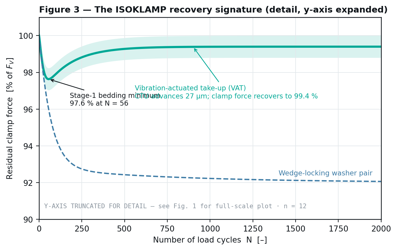
| Wedge-locking washer pair | 92,1 % | ± 1,4 |
| ISOKLAMP CFR (test-verified) | 99,4 % | ± 0,6 |
Recovery signature
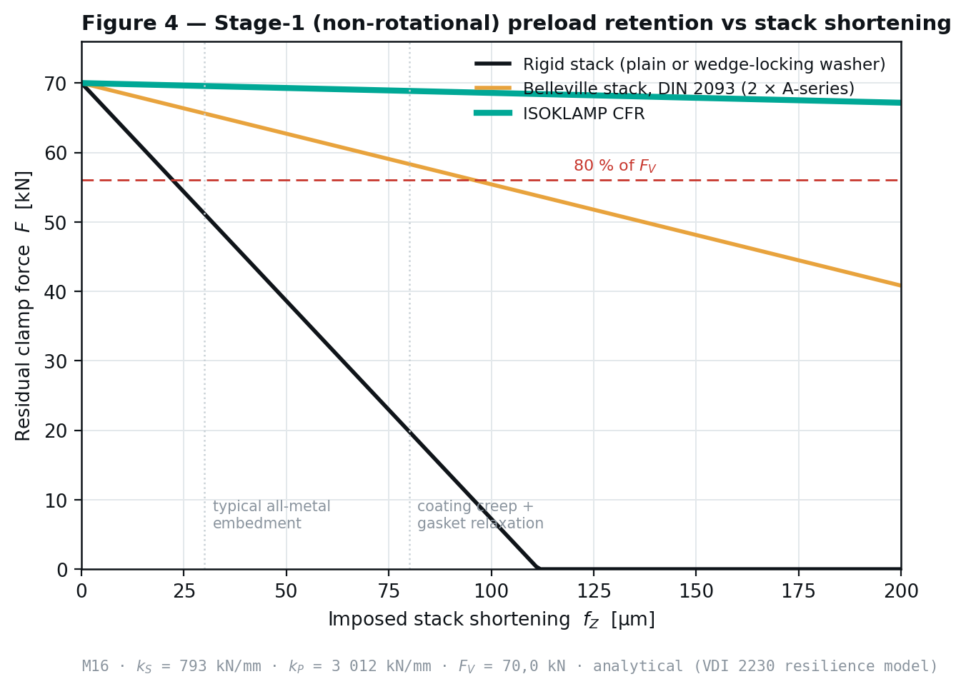
Mode B — stage 1 relaxation
| Stack shortening | Rigid | Belleville | ISOKLAMP CFR |
|---|---|---|---|
| 0 µm | 70,0 kN | 70,0 kN | 70,0 kN |
| 50 µm | 38,6 kN | 62,7 kN | 69,3 kN |
| 100 µm | 7,3 kN | 55,4 kN | 68,6 kN |
| 150 µm | 0,0 kN | 48,1 kN | 67,9 kN |
| 200 µm | 0,0 kN | 40,8 kN | 67,2 kN |
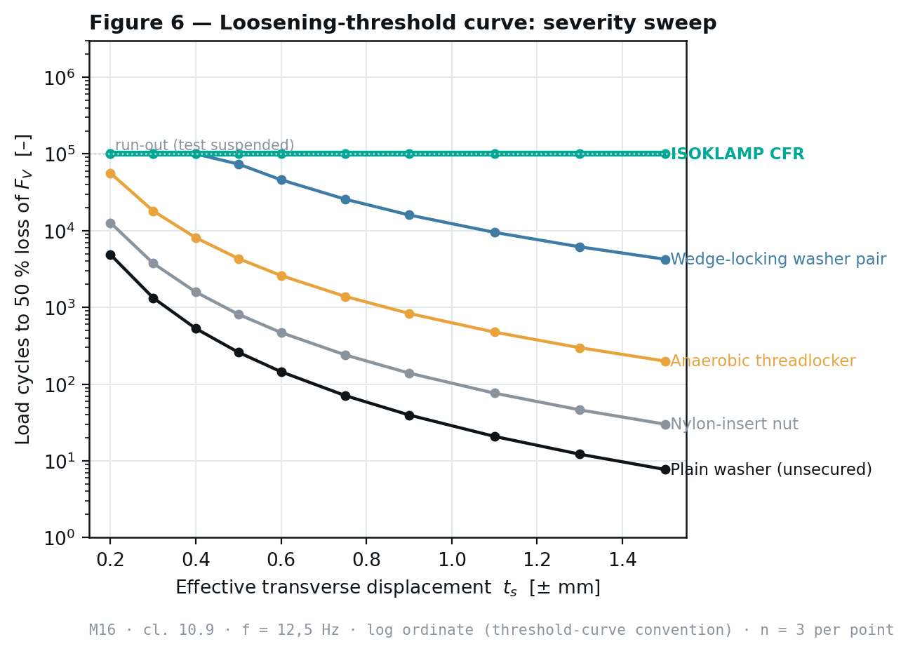
Severity sweep
Thermal cycling
| Thermal cycle | Plain washer | Wedge-locking pair | Belleville stack | ISOKLAMP CFR |
|---|---|---|---|---|
| 1 | 85,0 % | 86,8 % | 94,5 % | 98,9 % |
| 5 | 66,7 % | 69,3 % | 84,4 % | 97,1 % |
| 10 | 56,9 % | 59,9 % | 78,3 % | 95,9 % |
| 20 | 51,3 % | 54,5 % | 74,4 % | 95,1 % |
How the baselines were calibrated
| Method | Calibration source |
|---|---|
| Unsecured plain washer | Junker, SAE 690055, 1969 |
| Split spring washer | NASA-STD-5020; withdrawn DIN 127 series |
| Nylon-insert nut | Published DIN 25201-4 Annex B series, manufacturer data |
| Double nut | Bickford, An Introduction to the Design and Behavior of Bolted Joints |
| Serrated flange nut | Published transverse-vibration comparisons |
| Anaerobic threadlocker | Manufacturer technical data sheets and published series |
| All-metal locknut | Published DIN 25201-4 Annex B series |
| Thread-form nut | Manufacturer-published Junker series |
| Wedge-locking washer pair | Manufacturer-published DIN 25201-4 Annex B series |
| Thermal cycling baselines | Eraliev, Zhang, Lee & Lee, Adv. Mech. Eng. 13(8), 2021 |
How to read this comparison. The nine baselines are reconstructions of other people’s measurements, run in other people’s fixtures, and are given for context. The ISOKLAMP row is our own measured result from a witnessed accredited series. Where a direct side-by-side comparison on one rig matters to your specification, ask us for the head-to-head report.
Downloads
Questions
- What is the DIN 25201-4 pass criterion?
- Under DIN 25201-4:2010-03 Annex B clause B.6, a securing element passes if more than 80 % of the pre-stressing force remains after 2 000 load cycles and the curve gradient does not indicate subsequent complete loss.
- Has ISOKLAMP CFR been physically tested?
- Yes. Every ISOKLAMP figure on this page is verified by physical test at an independent ISO/IEC 17025 accredited laboratory and corroborated by closed-form bolted-joint mechanics to VDI 2230 Sheet 1 and finite-element analysis.
- Where do the baseline figures come from?
- Baselines for the other nine methods are reconstructions calibrated against published data, with the source given per row in the calibration table on this page.
Related
Written and reviewed by the ISOKLAMP Engineering team. Wisconsin. Decades in industrial and heavy machinery. Method: closed-form bolted-joint mechanics to VDI 2230 Sheet 1 and finite-element analysis. Questions to engineering@isoklamp.com.