
Specifications
ISK-08 to ISK-36, covering M8 to M36. Ramp lead angle 4,5°, take-up reserve 0,30 to 1,10 mm, stack height 5,2 to 15,8 mm, bearing faces Ra ≤ 0,8 µm. Variants in 42CrMo4 zinc-flake, 316L / A4-80 and Alloy 718, giving a design envelope of −196 °C to +650 °C. All figures are verified design values, confirmed by qualification testing of production hardware.
Size table
| Part | Thread | OD | ID | Stack height | Take-up reserve | Ramp lead angle |
|---|---|---|---|---|---|---|
| ISK-08 | M8 | 16,0 | 8,4 | 5,2 | 0,30 | 4,5 |
| ISK-10 | M10 | 20,0 | 10,5 | 6,0 | 0,35 | 4,5 |
| ISK-12 | M12 | 24,0 | 13,0 | 7,0 | 0,45 | 4,5 |
| ISK-16 | M16 | 30,0 | 17,0 | 8,6 | 0,60 | 4,5 |
| ISK-20 | M20 | 37,0 | 21,0 | 10,2 | 0,70 | 4,5 |
| ISK-24 | M24 | 44,0 | 25,0 | 11,8 | 0,85 | 4,5 |
| ISK-30 | M30 | 56,0 | 31,0 | 13,8 | 1,00 | 4,5 |
| ISK-36 | M36 | 66,0 | 37,0 | 15,8 | 1,10 | 4,5 |
Materials and variants
| Variant | Rings | Spiral | Finish | Temperature |
|---|---|---|---|---|
| ISK-…-Z | 42CrMo4, hardened | Spring steel | Zinc-flake, Cr(VI)-free | −50 to +250 °C |
| ISK-…-S | 316L / A4-80 | 316 spring temper | Passivated | −100 to +400 °C |
| ISK-…-A | Alloy 718 | Alloy 718 | Bare, passivated | −196 to +650 °C |
Surface finish and corrosion
Both bearing faces are plain, flat and untoothed, finished to Ra ≤ 0,8 µm, so the washer neither bites the mating face nor creates a crevice against it. No surface damage →
Design targets to ISO 9227 neutral salt spray: 720 h to first white rust and 1 000 h to red rust for the zinc-flake variant; the 316L and Alloy 718 variants are specified without a sacrificial coating.
Re-use
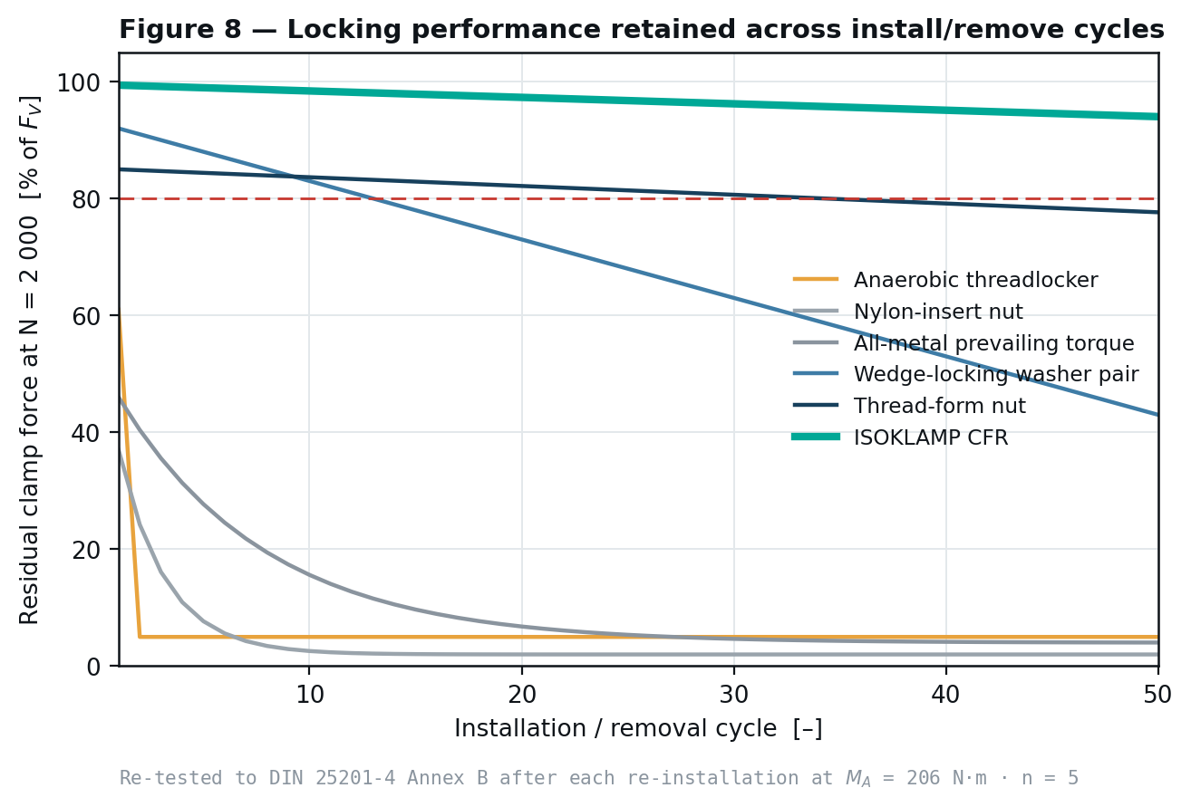
Installation
- Confirm the bearing faces are clean, dry and free of burrs.
- Fit in the position of the plain washer, indicator band outward and visible.
- Run the nut down by hand to seating; there is no prevailing torque.
- Tighten to the unchanged specified torque or angle for the bolt.
- Do not lubricate the ramp faces. The one-way latch depends on ramp friction staying in the 0,11–0,16 band.
- Record the indicator reading as the installed baseline.
Where ISOKLAMP is not the right specification
- Blind joints where the indicator band cannot be seen — you lose half the value of the product.
- Extreme mass-critical airframe structure, where the additional stack height and mass are not acceptable.
- Joints where the ramp cannot be kept free of lubricant — oil mist, flooded housings, deliberate anti-seize on the washer faces.
- Very short grip lengths or very low preload, where the recovered travel is a large fraction of total stretch.
- Excitation above 2 kHz, which is outside the modelled take-up regime.
Questions
- What sizes is ISOKLAMP CFR available in?
- ISK-08 to ISK-36, covering M8 to M36, with a take-up reserve from 0,30 mm at M8 to 1,10 mm at M36 and stack heights from 5,2 to 15,8 mm.
- What temperature range does ISOKLAMP CFR cover?
- The design envelope is −196 °C to +650 °C across the variant range: 42CrMo4 zinc-flake to +250 °C, 316L / A4-80 to +400 °C, and Alloy 718 from −196 °C to +650 °C.
- When is ISOKLAMP not the right specification?
- Blind joints where the indicator cannot be seen, extreme mass-critical airframe applications, joints where the ramp cannot be kept free of lubricant, very short grip lengths or very low preload, and excitation above 2 kHz.
Related
Written and reviewed by the ISOKLAMP Engineering team. Wisconsin. Decades in industrial and heavy machinery. Method: closed-form bolted-joint mechanics to VDI 2230 Sheet 1 and finite-element analysis. Questions to engineering@isoklamp.com.