
A self-locking helical take-up, biased by a constant torque
The four components
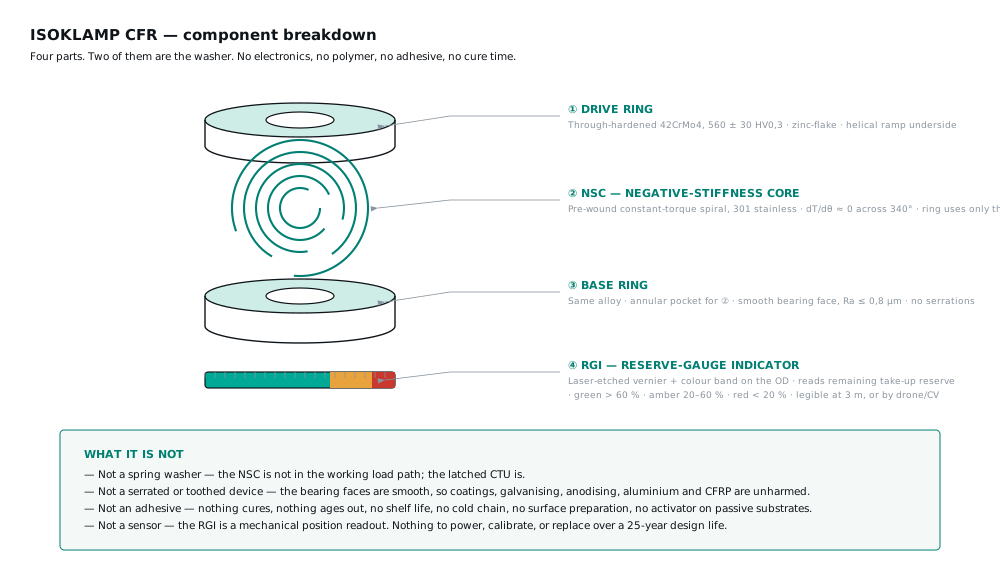
- Base ring — bears on the clamped part with a plain, flat, untoothed face.
- Drive ring — carries the matching multi-start helical ramp and bears on the nut or bolt head.
- Constant-torque spiral — pre-wound, supplies a near-constant rotational bias across the whole take-up travel.
- Reserve indicator band — the remaining take-up travel, readable from outside the joint. Reserve indicator →
The two inequalities
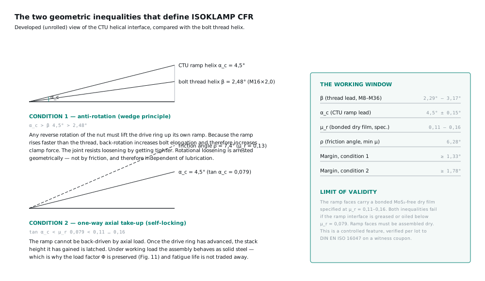
(1) α_c > α_t → 4,50° > 2,48° — the nut cannot back off
(2) tan α_c < µ_r → 0,079 < 0,11–0,16 — the take-up is one-way
The first inequality is the wedge-locking principle: to rotate loose, the nut would have to climb the ramp faster than the thread releases it. The second is what the incumbents do not have: below the friction limit the ramp cannot back-drive, so every increment of recovered stack height is latched.
Vibration-actuated take-up
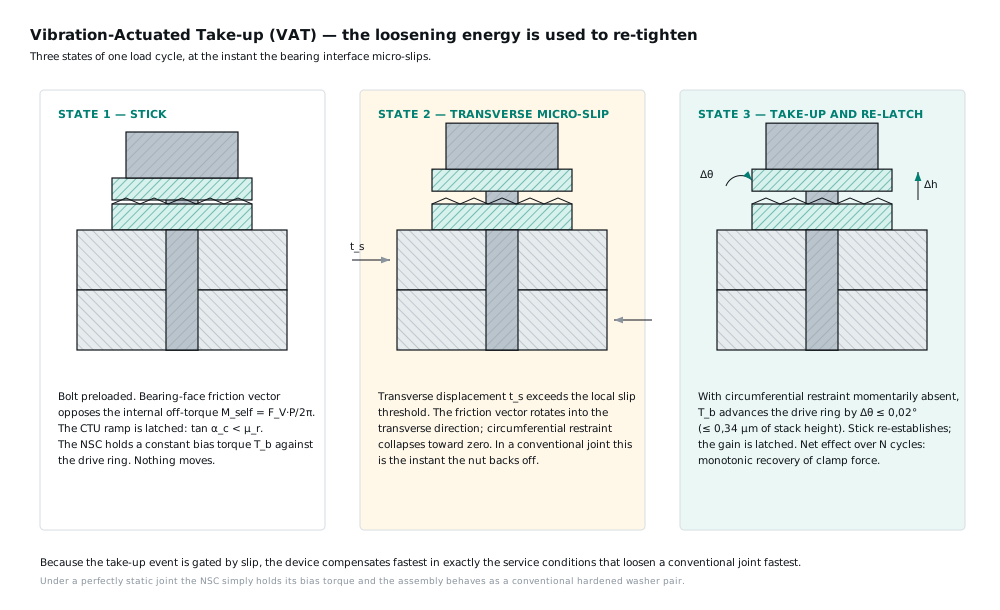
When a transverse load event momentarily reduces the friction holding the drive ring, the pre-wound spiral advances it a fraction of a degree up the ramp. The stack gets marginally taller, the bolt regains stretch, and when the load event passes the ramp latches at the new position. The disturbance that loosens a conventional joint is the same disturbance that tightens this one.
Take-up kinematics
(4) Δh = r_m · θ · tan α_c
(5) ΔF_V = Δh · (1/δ_S + 1/δ_P)⁻¹
(6) θ_max = h_reserve / (r_m · tan α_c)
Take-up travel Δh follows directly from the drive-ring rotation θ at the mean ramp radius r_m. The clamp force recovered is that travel divided by the resilience of bolt and clamped parts in series. Total reserve is fixed by the ramp height, which is the number printed against the indicator band.
Stiffness and load factor
| Configuration | Compliant direction | Load factor Φ |
|---|---|---|
| Rigid stack | None | 0,21 |
| Belleville stack | Both, permanently | 0,82 |
| ISOKLAMP CFR | One, then latched | 0,27 |
What it is not
Not a spring washer.
It does not rely on stored elastic deflection to hold load.
Not a toothed device.
Both bearing faces are plain and flat; no bite, no scoring.
Not a threadlocker.
No adhesive, no cure time, no shelf life, no single use.
Not a torque-indicating device.
It reads remaining compensation reserve, not installation torque.
Installation
- Confirm the bearing faces are clean, dry and free of burrs.
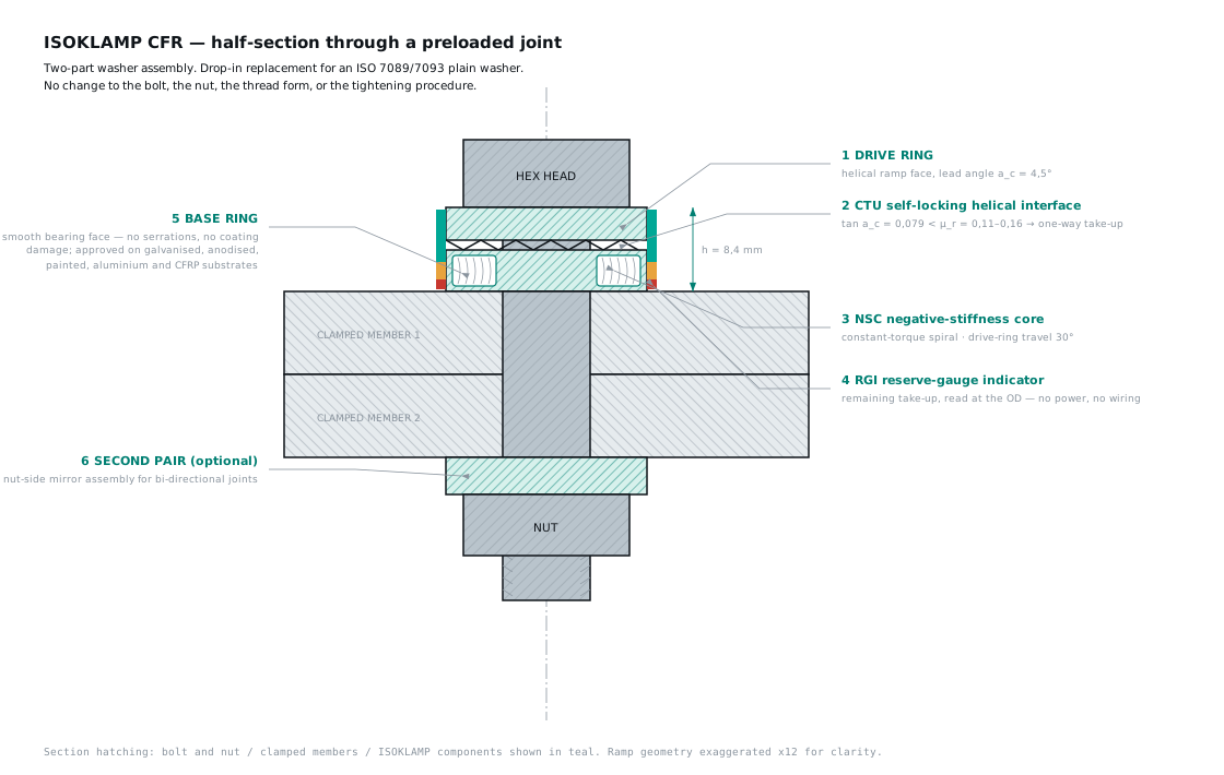
- Fit ISOKLAMP CFR in the position of the plain washer, indicator band outward and visible.
- Run the nut down by hand to seating; there is no prevailing torque.
- Tighten to the unchanged specified torque or angle for the bolt.
- Do not lubricate the ramp faces. The one-way latch depends on the ramp friction coefficient staying in the 0,11–0,16 band.
- Record the indicator reading as the installed baseline.
Section view
Questions
- How does ISOKLAMP CFR stop the nut backing off?
- The ramp lead angle exceeds the thread lead angle — 4,50° against 2,48° for M16 × 2,0 — so any rotation of the nut in the loosening direction would have to lift the stack faster than the thread releases it. The joint tightens against itself instead of releasing.
- Why is the take-up one-way?
- Because tan 4,5° = 0,079 is below the ramp friction coefficient of 0,11 to 0,16. The ramp cannot back-drive under axial load, so every increment of stack height gained is latched.
- Does it need a special bolt, nut or tool?
- No. ISOKLAMP CFR occupies the position of an ISO 7089 or ISO 7093 plain washer. Bolt, nut, thread form, tooling and tightening procedure are unchanged.
Related
Written and reviewed by the ISOKLAMP Engineering team. Wisconsin. Decades in industrial and heavy machinery. Method: closed-form bolted-joint mechanics to VDI 2230 Sheet 1 and finite-element analysis. Questions to engineering@isoklamp.com.