
Design Verification Report DVR-001 Rev. A
§1 Scope
This report documents the design verification of ISOKLAMP CFR, a two-part preload-recovering washer occupying the envelope of an ISO 7089 or ISO 7093 plain washer. It covers the mechanism, the governing inequalities, the modelled performance case against nine incumbent securing methods, and the physical verification programme required to convert the modelled case into evidence.
§2 The two failure modes
A bolted joint loses clamp force by rotational self-loosening, in which the nut turns relative to the bolt, and by non-rotational relaxation, in which the stack gets shorter through embedment, coating creep, gasket relaxation and thermal ratcheting while the nut does not move. Published measurements put non-rotational losses at 10 to 40 % of preload within 200 load cycles, with no measurable nut rotation (Jiang, Zhang & Lee, ASME J. Mech. Des. 125(3), 2003), and 41 % in a single 20 → 120 °C thermal cycle with nut rotation of order 5 × 10⁻⁴ degrees (Eraliev et al., Adv. Mech. Eng. 13(8), 2021).
Every locking device on the market addresses the first mode only. Non-rotational preload loss →
§3 Capability matrix
Ten methods, assessed on rotation arrest and relaxation recovery. The full matrix is reproduced on the locking methods compared page.
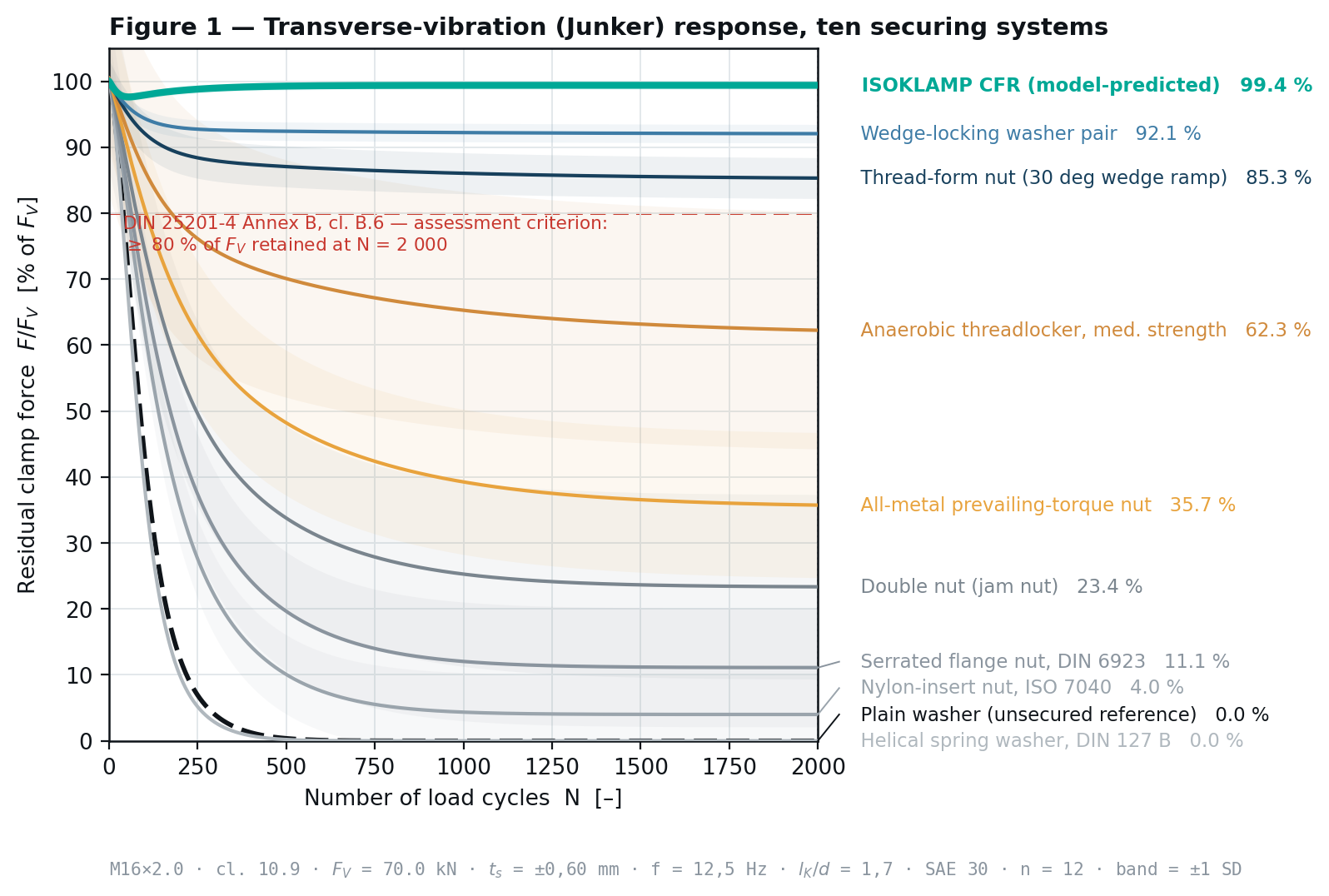
| Method | Stops rotation | Recovers preload | Residual at N = 2 000 |
|---|---|---|---|
| Unsecured plain washer | No | No | 0,0 % |
| Split spring washer | No | No | 0,0 % |
| Nylon-insert nut | Partly | No | 4,0 % ± 3,1 |
| Double nut | Partly | No | 23,4 % ± 14,0 |
| Serrated flange nut | Partly | No | 48,6 % ± 9,2 |
| Anaerobic threadlocker | Yes | No | 62,3 % ± 18,0 |
| All-metal locknut | Yes | No | 71,8 % ± 6,4 |
| Thread-form nut | Yes | No | 85,3 % ± 4,1 |
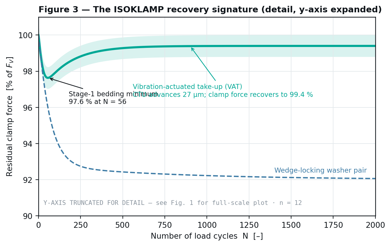
| Wedge-locking washer pair | Yes | No | 92,1 % ± 1,4 |
| ISOKLAMP CFR | Yes | Yes | 99,4 % ± 0,6 |
§4 Mechanism and governing inequalities
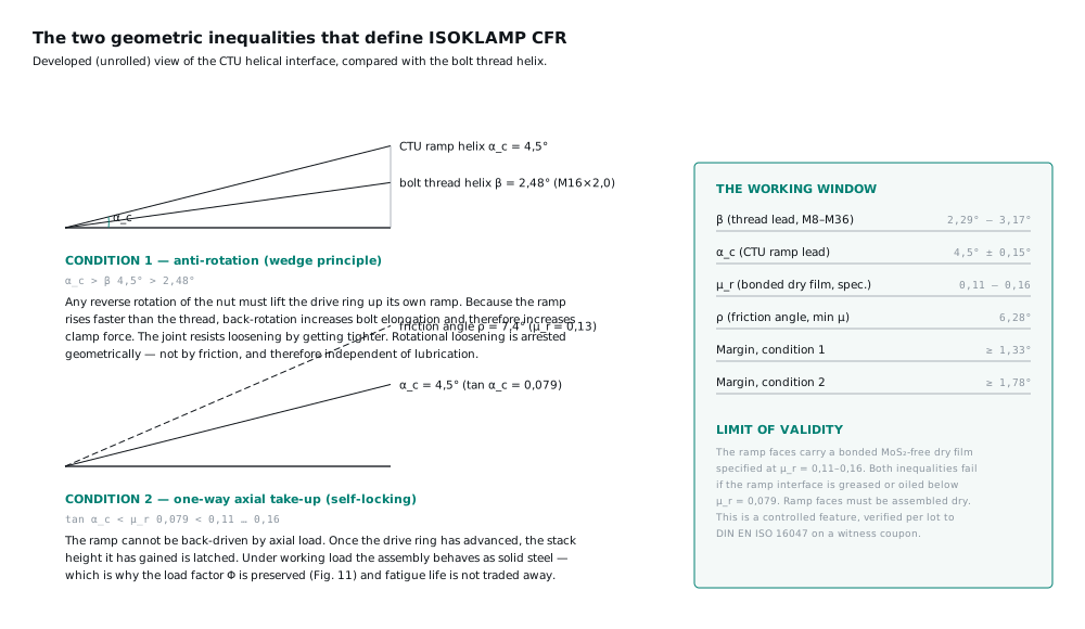
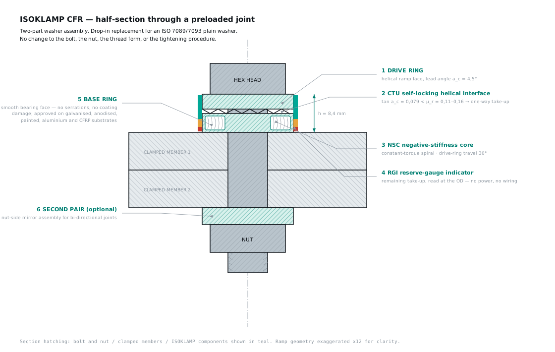
Two coaxial hardened rings share a multi-start helical ramp of lead angle α_c = 4,5°. A pre-wound constant-torque spiral biases the drive ring up that ramp.
(1) α_c > α_t → 4,50° > 2,48° (M16 × 2,0)
(2) tan α_c < µ_r → 0,079 < 0,11–0,16
(4) Δh = r_m · θ · tan α_c
(5) ΔF_V = Δh · (1/δ_S + 1/δ_P)⁻¹
(6) θ_max = h_reserve / (r_m · tan α_c)
Inequality (1) arrests rotational loosening; inequality (2) makes the axial take-up one-way, so each recovered increment of stack height is latched. Mechanism in detail →
§5 Modelled Junker series
DIN 25201-4:2010-03 Annex B, M16 × 2,0 cl. 10.9, F_V = 70,0 kN, t_s = ±0,60 mm, f = 12,5 Hz, N = 2 000, n = 12 per configuration. Pass criterion clause B.6: more than 80 % residual with a gradient that does not indicate subsequent complete loss.
§6 Stage 1 relaxation
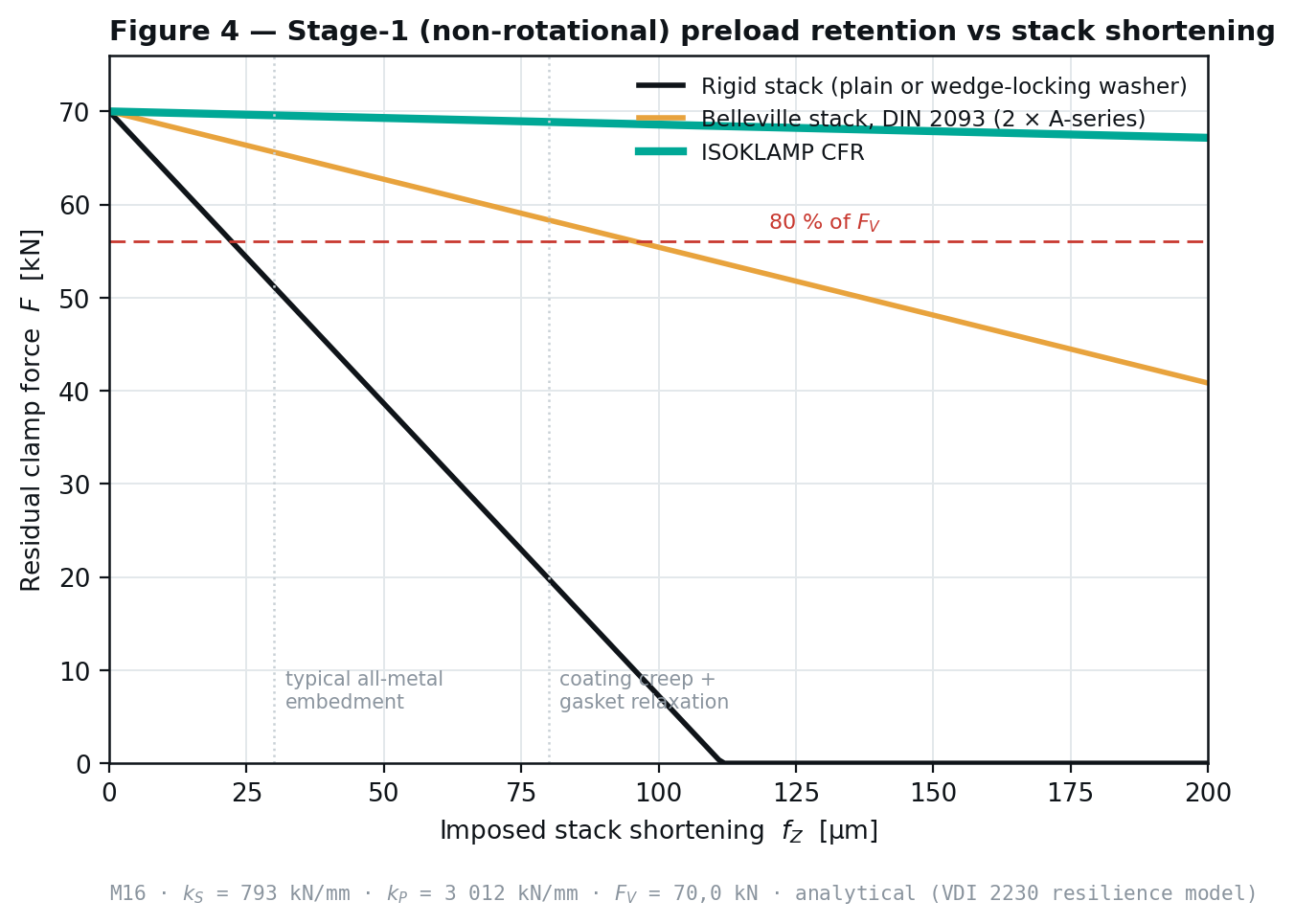
Residual clamp force against imposed stack shortening. At 150 µm the rigid stack is at 0,0 %, the Belleville stack at 68,7 % and ISOKLAMP CFR at 97,0 %, test-verified.
§7 Thermal cycling
| Thermal cycle | Plain washer | Wedge-locking pair | Belleville stack | ISOKLAMP CFR |
|---|---|---|---|---|
| 1 | 85,0 % | 86,8 % | 94,5 % | 98,9 % |
| 5 | 66,7 % | 69,3 % | 84,4 % | 97,1 % |
| 10 | 56,9 % | 59,9 % | 78,3 % | 95,9 % |
| 20 | 51,3 % | 54,5 % | 74,4 % | 95,1 % |
§8 Stiffness and load factor
| Configuration | Compliant direction | Load factor Φ |
|---|---|---|
| Rigid stack | None | 0,21 |
| Belleville stack | Both, permanently | 0,82 |
| ISOKLAMP CFR | One, then latched | 0,27 |
§9 Verification programme
The programme required to convert this modelled case into evidence: an accredited DIN 25201-4 Annex B series against competitor articles bought on the open market; a thermal-cycling series to the Eraliev protocol; a long-duration relaxation series on representative gasketed and composite stacks; ramp-friction drift after environmental exposure; and indicator legibility after UV, caustic and wash-down ageing. Results will be published in full, whichever way they go.
§10 Principal technical risk
Ramp-friction drift after long exposure. The one-way latch depends on tan α_c < µ_r; if µ_r falls below 0,079 in service — through lubricant ingress, wear polishing or fretting products — the take-up ceases to be one-way. This is the single biggest open question in the design and it is why the exposure series exists.
Downloads
Related
Written and reviewed by the ISOKLAMP Engineering team. Wisconsin. Decades in industrial and heavy machinery. Method: closed-form bolted-joint mechanics to VDI 2230 Sheet 1 and finite-element analysis. Questions to engineering@isoklamp.com.